When buried irrigation valves need maintenance or replacement, they can be difficult to find. Whether in valve boxes or buried unprotected, their location can be covered by dirt or mulch, or overgrown by grass. If the original system diagram is lost, or the sprinklers were installed by a previous homeowner, you need a method of locating your irrigation valves.
Automatic Sprinkler Valves
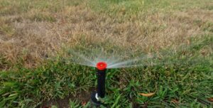
The irrigation valves control the water flow to the different zones of your system, with each valve being responsible for one area. The valves work by electricity, with wires leading from the irrigation controller to a solenoid on each valve. The controller sends an electric signal to the solenoid to turn on the valve. Inside the valve a diaphragm then opens that allows water to flow through the irrigation pipes. When the electric current is switched off, the diaphragm closes, shutting off the flow of water.
A valve can malfunction or stop working for a number of reasons, including damage to the wires or solenoid, a cracked body, ruptured or worn gasket, ruptured diaphragm, or dirt and debris in the components. Defective valves impact the health of your lawn, and in some cases cause inflated utility bills — a leaky valve can waste over 6,000 gallons of water a month.
Wire and Valve Locator
To inspect or repair a “lost” sprinkler valve you’ll first have to find it. One method that doesn’t damage your lawn is to use a wire and valve locator. This device is expensive to buy, and is mostly used by professionals, but homeowners can also rent one from sprinkler suppliers or tool rental outlets.
Basic Instructions for Using a Wire and Valve Locator
These instructions refer to an Armada Pro700 model, but the principles are similar for other models and brands. Some high-end wire and valve locators offer both an AC adapter and batteries as power options, digital displays rather than analog, and additional wireless connection methods. For your specific valve locator, be sure to follow the manufacturer’s instructions.
A basic wire and valve locator consists of a transmitter in a carrying case, a receiving wand, a set of black and red connecting leads, headphones, and a ground stake. You’ll also need eight “D” cell alkaline batteries for the transmitter, and one square 9-volt alkaline or lithium battery for the receiving wand.
Then, follow these steps:
- Remove the battery cover in the transmitter case and install the eight “D” cell alkaline batteries. Once the batteries are installed, replace the cover and turn on the transmitter with the power switch.
- Test the batteries by pushing the battery test button. You want a reading of 8 or more on the transmitter analog meter. After testing, turn the transmitter off.
- Install the square 9-volt battery in the receiver. Make sure to use an alkaline or lithium battery only, and not a zinc carbon or rechargeable lithium-ion battery. Turn the unit on and push the red battery test button on the underside of the receiver. The analog needle on top of the receiver should move to a reading of 10 or higher.
- Connect the headphones to the receiver. You can also hear the signal through the receiver’s external speaker.
- Warning before the next steps: Do not touch the red and black clips that connect the transmitter to the wire being traced when the power is on. On the controller find the wire leading to the targeted zone valve. Disconnect this wire and the common wire. Ensure the transmitter is off and plug the red lead into the red outlet on the transmitter. Then connect the red lead to the disconnected wire to be traced. Do not connect to the controller because the signal could cause damage if the controller’s not voltage protected.
- Plug the black lead (ground) into the black outlet on the transmitter and clip the other end to the ground stake. Insert the ground stake deeply into the earth perpendicular to the path of the wire, and as far from the transmitter as possible.
If the controller is inside, you may have to run an extension wire from the black lead to the ground stake. Use insulated copper wire and strip the insulation casing from the ends so there’s two inches of exposed wire. Clip the black lead to one end and wrap the other end around the ground stake. Insert the stake outside all the way into the earth.
- Test the transmitter by turning it on and adjust the power output knob until you get a reading between 4 and 8 on the meter. Don’t turn the power past 10 or you’ll waste battery power with no benefit in unit performance.
- Test the receiver by turning it on and placing it near the transmitter. Make sure it’s also turned on. You should hear a beeping sound. A high-pitched tone means you’re either too close to the receiver or your batteries are too low. A fading signal also indicates a low battery. On the front of the receiver an analog meter shows the signal reception strength.
- To begin tracing, make sure the transmitter and receiver are both on, and point the receiver toward the ground, gently sweeping the unit side to side. Listen for the beeping sound. The signal increases in volume to the immediate right and left of the wire you’re tracing, but when the receiver is directly over the wire there’s almost no sound (the null principle).
Finding a Valve
- Finding a valve when the red lead of the transmitter is connected to the valve’s station or zone wire, and the black lead to ground, is referred to as the “unbalanced” method.
- Begin where the wire enters the ground and follow the null (virtually no sound).
- If a wire is broken, you may not be able to follow it further until you repair it. The better locators can jump the signal over small wire breaks, allowing you to continue along to the valve.
- When you reach the point over the valve, the beeping expands into an area about 2-4 feet in diameter, and often gets louder.
- The signal will not usually continue past this area unless there are more valves on the wire being traced. You may want to check further for other valves located on the same wire.
Finding Wire Breaks or Damaged Wire
- Do not let the receiver level go above 10, or a drop in signal level may not be detected.
- A break in the wire will cause the signal to stop at the break point.
- A nick or damage to the wire will cause the signal level to drop.
- The receiver’s analog meter will also show a drop — the more damage, the more the signal will drop.
- A damaged area can also cause the signal to strengthen at the cut as it’s lost to ground.
- Minimal damage will show little change and is sometimes so small as to be unlocatable.
- Even if there’s no wire damage, slack loops of wire left underground during installation can cause an increase in signal.
Finding the Depth of a Wire
- Find the path of the wire (the null) and mark the ground above it.
- Stand to the left or right of the path and hold the receiver at a 45-degree angle, point it toward the wire.
- Slowly walk the receiver away from the wire path keeping the 45-degree angle until you reacquire the null. Mark the spot.
- The distance between the two marks is the approximate depth of the wire.
If that sounds like more than you want to take on as a DIY project, call us. One of the many irrigation repair services that South Austin Irrigation provides is valve locating, repair, and maintenance.
You can reach us at (512) 534-7449 or online.